
In this entry of the fan controller project series, I’m diving into the work I completed around part selection and schematic capture. This stage sets the foundation for everything that comes next—PCB layout, firmware development, and eventual testing. Here’s a quick look at my workflow in KiCad along with a breakdown of the components I selected and why.
Schematic Capture in KiCad
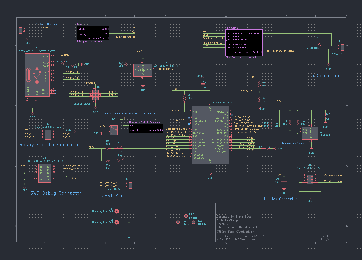
For this project, I used KiCad version 9, the latest version of the open-source EDA tool—and it continues to impress. Over the years, KiCad has evolved from a hobbyist’s utility into a serious, professional-grade design environment. With each major release, it keeps getting better with full support for all 3 major OS platforms (Windows, Mac and GNU/Linux Distros). KiCad handled all of my schematic capture and PCB design tasks. I even used it to sketch the initial block diagram before connecting symbols. There are paid alternatives that have some special features, but I have not personally come up against any issues that required me to use those paid packages. I think the world of this software and I’m super appreciative that it exists. I make an effort to make a modest donation to them every year and I encourage you to do the same if you feel that this software provides you any value.
Here’s an overview of how I designed this project in KiCad:
- Sketch out system blocks in KiCad’s schematic editor (MCU, sensors, fan control, etc.)
- Drop in components from the built-in libraries (or create custom symbols when needed)
- Wire components logically, organizing by function
- Run Design Rule Checks to make sure I connected all the components correctly.
- Use KiCad’s automatic reference designator assignment to label parts that can be referenced when hand assembling the finished PCB and for navigating the layout when troubleshooting.

Microcontroller Selection
For the brains of the operation, I chose an STM32 microcontroller (MCU) – specifically one from the STM32G0 series. I needed something with:
- A timer with PWM support to control the fan speed
- I2C support for communicating with the temperature sensor and display
- Low power consumption
- A USB peripheral for communication with a PC
- UART support for additional output and general debugging
- Affordable and widely available in small quantities
The goal here was to pick something reliable, cost-effective, and easy to integrate into future revisions or kits.
Power Switchover Circuit
The board can be powered either through USB-C or from an external battery (via a power connector). I implemented an automatic power switchover circuit to handle this seamlessly. This is controlled by the TPS2116, a 2 channel power mux that can automatically switch over to an alternate power source if there is a large voltage drop on either of two voltage inputs and can be manually switched with the help of the MCU.
I may write a dedicated blog post on this later—it’s a useful little device for many embedded designs.
USB-C Interface
While I don’t need high-speed data transfer, I wanted a modern and reversible power connector. I chose a basic USB-C implementation, with resistors on the CC lines to negotiate 5V. This setup keeps things simple and avoids the need for a USB controller IC.
Later in the design, I plan on exploring USB communication with the PC, but for now, it’s strictly for power delivery.
User Mode Switch with Analog Debouncing circuit
There’s a physical slide switch that lets the user select between different operating modes.
To debounce the switch in hardware, I used:
- An RC low-pass filter
- A Schmitt-trigger inverter
- A Schottky Diode
The RC network adds a low pass filter on the front end to dampen high frequency switching noise caused the mechanical switching action. The Schottky diode allows for a symmetric time constant for both the charge and discharge times of the capacitor of the RC filter. This means turn on and turn off times are equal. The Schmitt trigger inverter is used for hysteresis, so that a small voltage fluctuation won’t cause a transition from one to zero, unless there is a large enough voltage change. This cleans up noisy transitions from the switch before they reach the MCU, freeing the firmware from debouncing logic. There is a great article about this by Clive Maxfield on Digikey’s website.
Temperature Sensor: HDC1080
For temperature sensing, I went with the HDC1080. It features:
- Digital I2C interface
- A relatively small surface-mount footprint
- Accurate enough for fan control purposes
- Low-power idle mode
The HDC1080 gives the microcontroller temperature feedback to adjust fan speed and LED behavior.
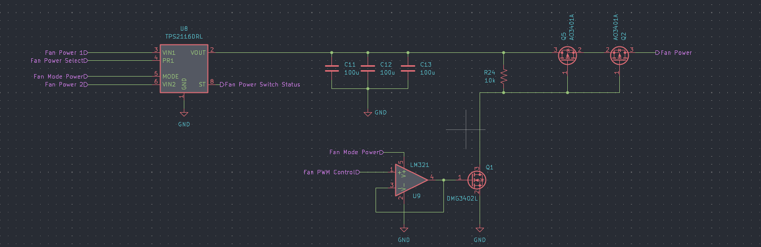
PWM-Controlled Fan Power Circuit
One of the core features of this controller is its ability to modulate power to a DC fan using Pulse Width Modulation (PWM). PWM is fixed frequency output that has an adjustable width of time for each pulse. A more narrow pulse will produce a lower average signal output which translates to less power delivery to the DC motor controlling the fan.
Here’s how it works:
- The STM32 outputs a PWM signal to a digital buffer that drives the gate of an N-channel MOSFET.
- The N-Channel MOSFET can pull down the gates of two P-channel MOSFETs arranged in parallel.
- These P-Channel MOSFETs act as high-side switch that connect power to the fan’s DC motor
- By varying the PWM duty cycle, the MCU can control fan speed proportionally to the temperature
- The Fan’s power can be sourced from the battery or the USB C connector, depending on the control signal from the MCU.
This approach is efficient, simple, and keeps power dissipation low. I chose P-channel parts for high-side switching simplicity, despite their slightly higher Rds(on) compared to N-channel counterparts.
What’s Next?
With part selection done and the schematic complete, I’ll be moving on to PCB layout next. This is where the electrical design turns into a physical product, and I’ll cover part placement, fan connector routing, and power path considerations. There are also a couple of connections that I left out that may be up for discussion in a future post (rotary encoder switch and debug adapter).
If you’re following the series, feel free to leave feedback or questions—I’m always happy to share more detail or explore alternate design paths in future posts.
Leave a Reply